


Inspection is a critical part of PCB assembly quality control. As board density increases and packages like BGA and QFN become common, relying on a single inspection method is rarely sufficient.
AOI, X-ray, and ICT each serve a different purpose in PCBA inspection. Understanding their strengths and limitations helps manufacturers choose the right inspection strategy without unnecessary cost.
Why PCB Assembly Inspection Matters
PCB assembly defects often originate during solder paste printing, placement, or reflow. Without effective inspection, these defects can pass undetected into functional testing—or worse, into the field. A well-designed inspection plan improves first-pass yield, reduces rework, and protects long-term product reliability.
No single inspection method can detect every defect. In practice, manufacturers combine AOI, X-ray, and ICT based on product complexity, risk level, and production volume.
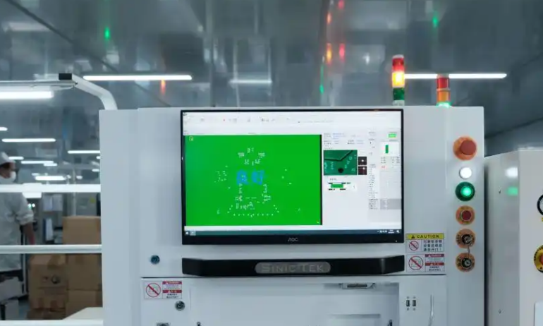
::contentReference[oaicite:0]{index=0}What Is AOI (Automated Optical Inspection)?
How AOI Works
AOI uses high-resolution cameras and image-processing algorithms to visually inspect assembled PCBs. The system compares captured images against reference data to identify visible defects.
Defects AOI Can Detect
Missing or incorrect components
Polarity and orientation errors
Solder bridges and insufficient solder
Component misalignment or skew
Strengths of AOI
Fast and highly automated
Cost-effective for most SMT assemblies
Excellent coverage for visible solder joints
Provides immediate process feedback
Limitations of AOI
Cannot see hidden solder joints
Limited effectiveness for BGA and bottom-terminated packages
False calls if programming is not optimized
What Is X-Ray Inspection?
How X-Ray Inspection Works
X-ray inspection uses penetrating radiation to visualize internal solder joints that are hidden from optical inspection. It is essential for packages where solder joints are located underneath the component body.
Defects X-Ray Can Detect
BGA and QFN solder joint voids
Open or shorted hidden connections
Insufficient solder volume under components
Head-in-pillow and non-wetting defects
Strengths of X-Ray Inspection
Only practical method for inspecting hidden joints
Critical for high-density and high-reliability designs
Provides insight into solder joint quality
Limitations of X-Ray Inspection
Higher equipment and operating cost
Slower throughput than AOI
Often sampled rather than applied to every board
What Is ICT (In-Circuit Test)?
How ICT Works
ICT electrically tests individual nodes on a powered or unpowered PCB using probes or a bed-of-nails fixture. It verifies that components are present, connected correctly, and within expected electrical values.
What ICT Can Detect
Open and short circuits
Incorrect component values
Missing or wrong components
Basic functional faults at the circuit level
Strengths of ICT
Excellent electrical fault coverage
Highly repeatable and objective results
Ideal for stable, high-volume production
Limitations of ICT
Requires custom fixtures
Limited access on dense or miniaturized boards
Less suitable for early prototypes
AOI vs X-Ray vs ICT: Practical Comparison
Inspection Coverage
AOI: Visible defects and placement errors
X-Ray: Hidden solder joints and internal defects
ICT: Electrical connectivity and component values
Cost and Speed
AOI: Lowest cost per board, fastest throughput
X-Ray: Higher cost, typically used selectively
ICT: High upfront fixture cost, low per-unit cost at volume
How to Choose the Right Inspection Strategy
The best inspection strategy depends on product complexity and risk tolerance. A practical guideline:
Simple SMT boards: AOI + basic functional test
BGA/QFN designs: AOI + X-ray + functional test
High-volume production: AOI + ICT + selective X-ray
High-reliability products: AOI + X-ray + ICT + full functional testing
Common Inspection Strategy Mistakes
Relying on AOI alone for BGA-heavy designs
Skipping inspection to reduce short-term cost
Adding ICT too early in prototype stages
Over-testing low-risk products unnecessarily
Conclusion
AOI, X-ray, and ICT are complementary—not competing—inspection methods. AOI catches visible defects quickly, X-ray reveals hidden solder issues, and ICT validates electrical integrity. Selecting the right combination based on product risk, volume, and complexity is essential for achieving reliable PCB assembly without excessive cost.
FAQ
Is AOI enough for modern PCB assemblies?
AOI is essential, but it is not sufficient for designs with hidden solder joints. BGA and QFN packages typically require X-ray inspection for full coverage.
Should every board go through X-ray inspection?
Not always. Many manufacturers apply X-ray inspection selectively or by sampling, depending on risk level and production volume.
When does ICT make the most sense?
ICT is most effective in stable, high-volume production where fixture cost can be amortized and electrical coverage is critical.