


Choosing between SMT PCB assembly and through-hole assembly is a practical decision that affects cost, reliability, manufacturability, and long-term product performance. While modern electronics rely heavily on SMT, through-hole technology (THT) still plays a critical role in many designs. This article provides a clear, engineer-focused comparison to help you select the right assembly method for your application.
SMT PCB Assembly vs Through-Hole Assembly at a Glance
SMT (Surface Mount Technology): Components are mounted directly onto the PCB surface using solder paste and reflow.
Through-Hole (THT): Components are inserted through drilled holes and soldered on the opposite side.
Both technologies are widely used today—often together on the same board. The “better” option depends on electrical, mechanical, and production requirements rather than trends alone.
::contentReference[oaicite:0]{index=0}What Is SMT PCB Assembly?
SMT PCB assembly places components directly onto surface pads using automated pick-and-place machines. After placement, the board passes through a reflow oven where solder paste melts and forms electrical and mechanical connections.
Key Characteristics of SMT
No drilled component holes required
Supports very small and fine-pitch components
Highly automated and scalable
Enables double-sided component placement
Typical SMT Components
Chip resistors and capacitors (0402, 0603, etc.)
QFN, BGA, LGA, SOIC, TSSOP ICs
RF modules and high-pin-count processors
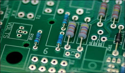
What Is Through-Hole Assembly?
Through-hole assembly involves inserting component leads into drilled holes and soldering them, typically using wave soldering or selective soldering. The solder joint anchors the lead through the PCB, providing strong mechanical support.
Key Characteristics of Through-Hole
Excellent mechanical strength
Handles higher current and voltage well
More tolerant of mechanical stress and vibration
Less sensitive to pad size and solder volume variation
Typical Through-Hole Components
Large electrolytic capacitors
Connectors and headers
Transformers, inductors, relays
Terminal blocks and power devices
Detailed Comparison: SMT vs Through-Hole
1) Board Density and Size
SMT clearly wins in terms of component density. Because parts mount on the surface and can be placed on both sides, SMT allows significantly smaller and lighter boards. Through-hole components require drilled holes and keep-out areas, increasing board size.
2) Mechanical Strength
Through-hole assembly provides superior mechanical anchoring, making it ideal for connectors, cables, and parts exposed to frequent physical stress. SMT solder joints are reliable but more sensitive to shock if large forces are applied directly to the component.
3) Electrical Performance
SMT components typically have shorter leads, which reduces parasitic inductance and capacitance. This improves high-frequency and high-speed performance. Through-hole parts may introduce longer current paths, which can matter in RF or fast-switching designs.
4) Manufacturing Speed and Cost
SMT assembly is highly automated and cost-effective for medium to high volumes. Once the line is set up, placement speed is extremely high. Through-hole assembly often requires manual insertion or additional soldering steps, increasing labor cost—especially at scale.
5) Prototyping and Rework
Through-hole components are easier to hand-solder, remove, and replace, making them popular in early prototypes and educational projects. SMT rework requires hot-air tools, skill, and sometimes X-ray verification for hidden joints.
When SMT Is the Better Choice
Compact or lightweight products
High-volume production
High-speed or RF circuits
Consumer electronics and IoT devices
Boards with high component count
When Through-Hole Is the Better Choice
High-current or high-voltage paths
Components subject to mechanical stress
Industrial or harsh-environment electronics
Low-volume builds requiring frequent rework
Large connectors, transformers, or power devices
Mixed Technology: The Practical Reality
Many real-world designs use a mixed technology approach, combining SMT for signal processing and control circuits with through-hole parts for power and mechanical interfaces. In these cases, SMT is typically assembled first, followed by selective or wave soldering for through-hole components.
Mixed assembly offers an effective balance between compact layout and mechanical robustness, especially in industrial control, power supplies, and automotive electronics.
Design Tips When Choosing Between SMT and Through-Hole
Use SMT wherever mechanical stress is low and size matters
Reserve through-hole for connectors, heavy parts, and power paths
Align through-hole components to simplify wave or selective soldering
Consider assembly sequence early to avoid reflow or solder conflicts
Consult your PCBA partner during layout for DFA feedback
Conclusion
SMT PCB assembly and through-hole assembly are not competing technologies—they are complementary tools. SMT enables compact, high-performance, and cost-effective electronics, while through-hole assembly provides unmatched mechanical strength and robustness. Understanding the strengths and limitations of each allows engineers and procurement teams to make informed decisions that optimize performance, reliability, and total manufacturing cost.
FAQ
Is through-hole technology obsolete?
No. While SMT dominates modern electronics, through-hole components remain essential for power handling, mechanical durability, and certain industrial applications.
Can SMT boards handle high current?
Yes, with proper copper thickness, pad design, and thermal management. However, very high current connections are often still implemented using through-hole terminals or connectors.
Does mixed assembly increase cost?
Mixed technology can add process steps, but it often reduces overall risk by placing each component type where it performs best. In many designs, this tradeoff improves reliability more than it increases cost.